

Diameter steps in pneumatic conveying pipelines: the evaluation begins with defined process conditions, material data and equipment boundaries. A positive-pressure conveying gas expands as pressure falls toward the receiver. In a constant-bore line, actual gas volume and velocity can rise downstream. A larger downstream bore may limit that velocity, but the benefit depends on where and how the diameter changes.
Stepped-Bore Pipelines for Low-Pressure Pneumatic Conveying explains the overall purpose of stepped-bore pipelines. This page focuses on the next procurement question: how to locate a step so the new section remains stable without allowing excessive velocity to develop upstream.
What Happens Immediately After a Step
At a local transition where gas mass flow, pressure and temperature do not change greatly across the short fitting, the approximate velocity ratio is governed by area:
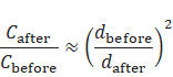
Increasing diameter therefore creates an immediate reduction in gas velocity. The velocity may begin rising again farther downstream as pressure continues to fall.
The critical value is not the high velocity just before the step; it is often the lowest loaded velocity immediately after the expansion. If that value falls below the material’s stable transport limit, particles can deposit and initiate a blockage.
Select Location from the Loaded Operating Window
Step location should be evaluated using:
- Actual bore before and after the transition.
- Local absolute pressure and gas temperature.
- Air mass flow or consistently referenced volume flow.
- Material-specific minimum stable velocity.
- Solids loading and conveying mode.
- Upstream bends, vertical sections and feeder behavior.
- Downstream receiver and filter pressure.
The step should not be positioned solely by equal pipe lengths or fabrication convenience. A long first section may permit unnecessarily high velocity and wear. An early step may reduce velocity before the material has enough momentum or before local pressure has fallen sufficiently.
Transition Geometry Matters
A controlled tapered transition usually provides a more predictable flow path than an abrupt enlargement. Sudden area changes can create recirculation zones where cohesive or heavy particles collect. Internal weld beads, misalignment and liner steps can make the disturbance worse.
The fabrication drawing should state the finished bore, transition length, internal surface requirement and inspection method. Site substitution of a concentric fitting with a different geometry should require process approval.
Check Every Governing Case
A step selected for full production may behave differently during startup, reduced material rate, filter loading or line purging. Lower blower speed can reduce velocity after the step; higher receiver pressure can alter expansion along the line. Purge flow may create a high downstream velocity even though no solids are present.
The operating study should include at least:
- Minimum approved conveying airflow.
- Normal loaded duty.
- Maximum airflow or purge duty.
- Clean and maximum normal filter resistance.
- Every route using the stepped section.
- Minimum and maximum product rate.
If no single step arrangement works across the required range, the process may need a different pipe bore, control strategy or route configuration.
Commissioning the Step
Pressure taps before and after major sections help establish whether the installed line matches the calculation. Commissioning should compare airflow, blower speed, pressure, material rate and receiver condition while observing signs of deposition, unstable flow or excessive impact.
An empty-line baseline is useful for identifying fabrication restrictions, but it cannot prove loaded stability. Representative product trials remain important where the material behavior or scale-up is uncertain.
Wear inspection should focus on the upstream small-bore section, the transition and the first downstream bend. A velocity problem may appear as fines, noise or filter load before it becomes a visible pipe failure.
Roots blower Selection for an Expanding Line
The step changes the system pressure-flow relationship but does not create conveying energy. The roots blower must supply enough inlet volume and differential pressure for the complete loaded route while remaining within its permitted speed, power and temperature envelope.
Glossary
Loaded velocity: Local conveying-gas velocity while material is being transported.
Post-step velocity: Gas velocity immediately downstream of a diameter transition.
Recirculation zone: Local region of reversed or circulating flow produced by geometry or separation.
Step location: Axial position selected for a deliberate change in pipeline bore.