

Pneumatic conveying with roots blowers is a highly effective method to move powders and granules through a closed pipeline using a gas stream, usually air. The pipeline replaces belts, buckets and screws, so the product stays enclosed, routing is flexible, and dust stays inside the pipe.
The air mover is where most of the cost and most of the operating problems sit. For low-pressure systems, that air mover is very often a Roots-type blower. This article explains why, where its limits are, and what has to be settled before a blower is specified.
Where Pneumatic Conveying Fits in Bulk Material Handling
Bulk material handling covers storage, feeding and transport of solids. Within it, pneumatic conveying is chosen when:
- the product is dusty, hygroscopic, toxic or otherwise needs containment,
- the route has bends, vertical sections or multiple pick-up and discharge points,
- floor space is limited,
- distances are moderate (typically tens to a few hundred metres, rarely beyond about 1.5 km).
It is a poor fit when throughput is very high over long distances, when the product is extremely abrasive or friable and cannot be handled at low velocity, or when power cost per tonne is the deciding factor. Pneumatic systems are energy-hungry compared with belt conveyors, and that is a design constraint, not a footnote.
The Four Zones of Any Pneumatic Conveying System
Every system, whatever the blower, has the same four zones:
- Air mover (blower, fan, compressor or exhauster) that supplies flow and pressure.
- Feeding and acceleration zone, where product at rest enters moving air. Rotary valves, venturi feeders, screw feeders and blow vessels live here.
- Conveying line, including bends, diverters and any stepped pipe sections.
- Gas-solids separation, typically a cyclone, a fabric filter or both.
The feeding zone is usually where the largest local pressure loss occurs, because stationary solids are suddenly accelerated to conveying speed. A blower sized without accounting for feeder losses, filter losses and rotary valve leakage will fall short in service.
Dilute Phase, Dense Phase and Why the Mode Decides the Air Mover
The air mover choice follows the conveying mode, not the other way round.
| Mode | Typical air velocity | Solids loading ratio (kg solids / kg air) | Typical air mover |
|---|---|---|---|
| Dilute phase (suspension flow) | about 11 m/s for fine powders to 16 m/s or more for granular material | up to about 15 | Fan, Roots blower, vacuum exhauster |
| Moving bed / plug flow (dense phase) | down to about 3 m/s | can exceed 100 for moving bed, around 30 for plug-type | Screw or reciprocating compressor, with blow vessels |
Dilute phase is where roots blowers dominate. The product is carried in suspension by drag, the pressure requirement is modest, and the system tolerates a steady, predictable air supply. Dense phase generally needs higher pressures than a roots blower can deliver, which is why it is normally paired with compressors and blow tanks.
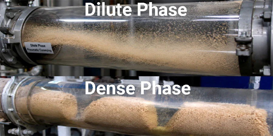
Be careful with the word “dense”. High pressure does not make a product convey in dense phase. Whether a material can be conveyed at low velocity depends mainly on its air retention and permeability, not on how much pressure is available.
Why Positive Displacement Suits Conveying Duty
The key operating characteristic is how air flow responds to line pressure.
- Fans and centrifugal machines: Air flow falls noticeably as line pressure drop rises. If the solids feed rate surges, pressure demand rises, air flow drops, and the pipeline can block.
- Positive displacement blowers (Roots type): Volumetric flow is largely independent of discharge pressure. A pressure surge causes only a small reduction in delivered air, limited to internal slip.
This matters because conveying systems run close to a minimum air velocity. In dilute phase, a drop of roughly 10 to 20 percent below that minimum is enough to risk blockage. A blower with a steep, near-flat flow characteristic gives the designer a defensible safety margin. That is the main engineering reason Roots blowers are the common partner of low-pressure rotary valves in dilute phase plants.
How a Roots Blower Works in This Duty
Two lobed rotors turn in opposite directions inside a casing. Air is trapped between lobes and the casing wall and carried from inlet to outlet. The air is not compressed inside the machine. Compression happens when the trapped volume opens to the discharge port and higher-pressure air flows back in.
Several practical consequences follow:
- Low thermodynamic efficiency at higher pressure ratios. Typical textbook figures for isentropic efficiency are about 0.94 at a pressure ratio of 1.2, about 0.84 at 1.6, and about 0.77 at 2.0. Efficiency falls as pressure ratio rises.
- Pressure ceiling. A single-stage Roots machine is generally limited to a compression ratio of about 2.3:1. At sea level that corresponds to roughly 1.3 bar gauge on pressure duty, and on the order of 0.5 bar of vacuum when used as an exhauster. Actual limits depend on the specific machine, speed and temperature, so use the manufacturer’s rating, not these round numbers.
- Internal slip. Leakage back through rotor clearances reduces delivered flow. Slip rises with differential pressure and falls with higher inlet air density, and it does not depend on speed. So at higher pressure or higher altitude, the machine must run faster to deliver the same free-air flow.
- Pulsation and noise. Three-lobe and twisted-rotor designs reduce both compared with two-lobe straight rotors.
- Oil-free air. Roots blowers deliver oil-free air because the rotors do not contact each other or the casing. This is relevant to food, pharmaceutical and chemical duties, and also to safety: oil carried into a conveying pipe can break down into carbon deposits that are prone to ignition.
Pressure, Vacuum and Combined Systems
Roots blowers can serve three system types.
Positive pressure systems. The blower pushes air into a feeder, typically a rotary valve, and material is delivered to one or several receivers via diverter valves. This arrangement suits multiple discharge points. Air leakage across the rotary valve must be added to the blower’s flow requirement, and the valve should be vented so leakage air does not disturb product flow from the hopper.
Vacuum (negative pressure) systems. The blower acts as an exhauster and material is drawn from multiple pick-up points to a single receiver. Leakage is inward, so dust release is minimal, which is useful for toxic or explosive materials. Two points need attention:
- The volumetric flow through a vacuum system is larger than for an equivalent pressure system because of air expansion, so filtration plant must be bigger.
- The exhauster must be protected from dust. A back-up filter downstream of the main filter is standard practice, since a failed filter element sends abrasive dust through the rotors.
Combined suck-blow systems. One blower serves a vacuum section and a pressure section. The available pressure ratio is shared between the two, so capacity and distance are limited compared with separate machines.
Practical Design Checks Before Specifying the Blower
A blower rating is only meaningful once the conveying duty is defined. In practice, the sequence looks like this.
1. Define the material. Particle size, particle and bulk density, shape, moisture, abrasiveness and friability all matter. Material properties decide the minimum conveying velocity, and no blower choice compensates for a wrong assumption here. Where the material is new, trials are the reliable route.
2. Set the pickup (inlet) air velocity. Take the minimum conveying velocity for the product and add margin. A margin of about 20 percent above the minimum is a common design allowance. Remember that air expands as pressure falls, so velocity rises toward the pipeline end. If the pressure drop is large, consider stepping the pipe to a larger bore to keep end velocity reasonable and limit wear and particle breakage.
3. Use absolute pressure and temperature. A frequent error is using gauge pressure in the velocity or density equations. The resulting inlet velocity is wrong, and the system may block on start-up.
4. Add up the pressure losses. The total includes the air-only pipe loss, acceleration of the solids, additional loss from the solids in horizontal and vertical sections, vertical lift, bends, the feeder, the cyclone or filter, and any valves. Bends are a common surprise, since the main loss from a bend comes from re-accelerating the solids downstream.
5. Include leakage. For positive pressure systems with a rotary valve, add the valve’s leakage flow to the blower’s delivered flow. Wear on the valve increases this leakage over time, which is why a pipeline that worked at commissioning can start blocking a year later.
6. Check temperature. Compressing air heats it. As an illustration, ambient air at 20 °C compressed to 1 bar gauge reaches roughly 84 °C even in an ideal process, and about 100 °C at 80 percent efficiency. Whether the product tolerates this depends on its melting point, moisture sensitivity and tendency to form streamers or “angel hair” in plastics. If the discharge air is too hot, an aftercooler or a lower pressure ratio is needed.
7. Estimate the power. A rough isentropic estimate for adiabatic compression is:
Adiabatic Compression Formulation
with p in kPa absolute and V in m³/s giving kW. For 1 m³/s of inlet air compressed from 101.3 kPa to 152 kPa absolute (pressure ratio 1.5), the ideal power is about 44 kW. Shaft power is higher after dividing by efficiency, so roughly 50 kW at about 0.85. Treat this as a screening number, not a motor selection. The manufacturer’s performance curves should govern the final choice.
8. Correct for altitude and temperature. Lower inlet density reduces mass flow and increases slip. A site at 1,500 m has a barometric pressure of about 840 mbar, and a blower rated at sea level will deliver less mass flow there unless speed is adjusted.
Where the Blower’s Responsibility Ends
A Roots blower provides a stable volume of air at a given pressure. It does not:
- decide whether a product can be conveyed in dilute phase,
- prevent wear in bends, valves or the pipeline,
- compensate for an undersized filter or a leaking rotary valve,
- make a long-distance or dense phase duty feasible outside its pressure range.
The process engineer or system designer remains responsible for the conveying mode, minimum velocity, pipeline layout and separator selection. A good supplier will review the application data, but the blower should not be the only thing validated. For an unfamiliar material, conveying trials on a test rig are more reliable than calculation alone.
Roots blowers also have clear limits on pressure. If the calculated system pressure drop approaches the machine’s rated differential, the right answer is usually a different air mover (screw or reciprocating compressor, or a blow-tank system), not a larger Roots blower pushed past its design range.
Operating and Troubleshooting Notes
- Monitor pressure near the pipeline start. A gauge before the feeder shows trends early. A rapid rise to blower pressure at start-up suggests overfeeding. A rising air-only pressure over time points to build-up or condensation in the pipe.
- Check air velocity first when diagnosing problems. Low velocity blocks lines. Excessive velocity reduces capacity, wears bends and breaks fragile particles.
- Watch for gradual blower wear. Abrasive dust ingress or worn rotor clearances reduce delivered air. A line that blocks “for no reason” months after commissioning often has a drifting air supply.
- Keep filters maintained. In vacuum systems, a damaged filter element is a direct threat to the exhauster.
- Do not raise the solids rate without raising the air rate. The pressure minimum line has a positive slope, so higher solids throughput needs a higher conveying velocity to stay stable.
When Pasifik Blower Roots Machines Are a Reasonable Fit
Pasifik Blower manufactures industrial Roots-type (rotary lobe, positive displacement) blowers. In pneumatic conveying, such machines are appropriate for dilute phase pressure systems at low to moderate pressure ratios, and for vacuum pick-up or vacuum conveying within the vacuum range of the machine. They are less suitable for dense phase systems that need pressures beyond a single Roots stage.
If you have a conveying application, the information that lets us give a useful answer includes: material and bulk density, required throughput, pipeline length, number of bends and vertical rise, feeder type, site altitude and ambient temperature, and whether the system is pressure or vacuum. With that data, a duty point can be checked against the blower’s performance curve rather than guessed.
Glossary
Dilute phase conveying: Transport of solids suspended in a high-velocity air stream, usually at low solids loading ratios.
Dense phase conveying: Transport at low velocity as a moving bed or as plugs, with high solids loading.
Solids loading ratio: Mass flow of solids divided by mass flow of conveying air. Dimensionless.
Saltation velocity: Air velocity below which solids begin to drop out of suspension in a horizontal pipe.
Pressure minimum: The point on a pressure-gradient versus air-velocity curve below which pressure drop rises again as velocity falls. The system becomes unstable beyond it.
Positive displacement blower: A machine that delivers a nearly fixed volume per revolution regardless of discharge pressure. Roots blowers belong to this group.
Slip: Internal leakage from discharge back to inlet through rotor and casing clearances.
Pressure ratio: Absolute discharge pressure divided by absolute inlet pressure.
Exhauster: A blower or pump used on the suction side to create vacuum, drawing air and product through a system.
Rotary valve (airlock): A bladed rotor in a housing that meters solids into a pipeline while limiting air leakage.
Free air: Air at site ambient pressure and temperature, used as the reference for flow ratings.
Stepped pipeline: A conveying line that increases in diameter along its length to control air velocity as the air expands.
Frequently Asked Questions
Can a Roots blower be used for any pneumatic conveying system?
No. It suits dilute phase systems at modest pressure or vacuum. Dense phase and long-distance duties usually need higher pressures than a single-stage Roots machine provides.
What is the typical pressure limit of a Roots blower in conveying duty?
As a general guide, a compression ratio of about 2.3:1, or roughly 1.3 bar gauge at sea level for pressure duty. Actual limits depend on the model and operating conditions, so always check the manufacturer’s rating.
Why is a Roots blower preferred over a fan for conveying?
Its air flow stays nearly constant as line pressure rises, which protects the minimum conveying velocity during pressure surges. A fan’s flow falls as pressure rises, which increases blockage risk.
Does using a Roots blower in a vacuum system change the filter requirement?
Yes. Air volume at the filter is larger under vacuum, so filtration area must be larger, and a back-up filter should protect the blower from dust.
How hot will the conveying air be?
It depends on pressure ratio, efficiency and inlet temperature. Air compressed from 20 °C to 1 bar gauge can reach about 100 °C in practice. Check product tolerance and consider cooling if necessary.
Can the blower prevent pipeline blockages?
It can support stable air flow, but blockages usually trace back to low air velocity, overfeeding, worn rotary valves, build-up in the pipe, or an unsuitable conveying mode for the material.
Is it better to oversize the blower for safety?
Not as a rule. Oversizing raises air velocity, which increases wear, breakage and power use. Size the air flow to the verified minimum velocity plus a defined margin.