

Rotary valve rotor selection: the evaluation begins with defined process conditions, material data and equipment boundaries. The rotor is the working element of a rotary airlock valve. Its end construction, pocket depth, blade geometry and clearances influence material capacity, gas leakage, pocket release, wear and product damage. Selecting a valve by connection size alone can therefore create a feeder that fits the pipe but does not fit the process.
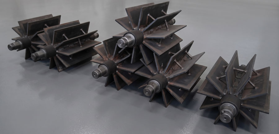
Open-End and Closed-End Rotors
An open-end rotor leaves the pocket ends open toward the valve side covers. The geometry can simplify construction and cleaning in suitable applications, but material and gas interact with the end-clearance region.
A closed-end rotor incorporates end plates that define the pocket sides. It can alter gas-leakage paths and reduce direct product entry into some end regions. Closed ends do not make the valve gas tight; tip and end clearances, shaft regions and empty pockets still permit leakage.
The choice should consider cleaning access, material retention, pressure difference, temperature expansion and service procedures.
Deep and Shallow Pockets
Deep pockets provide greater geometric volume per revolution, but theoretical volume is not the same as actual feed rate. Cohesive powder may bridge over the inlet or remain in a deep pocket. High rotor speed can reduce filling time, while pressure-driven gas can displace material before the pocket reaches the outlet.
Shallow pockets may release difficult material more readily and can produce smaller solids pulses. They also transfer less geometric volume per revolution. The optimum depth depends on repeatable filling and emptying with the real product.
Rotor Blades and Replaceable Tips
Replaceable blade tips can provide a maintainable wear surface and allow controlled clearance restoration. The tip material must be compatible with temperature, abrasion, product-contact and hazardous-area requirements.
Tighter clearance may reduce leakage, but it increases sensitivity to thermal growth, shaft deflection and product buildup. Flexible or specialized tips should not be selected solely for sealing without confirming mechanical and product safety.
Particle Shearing and Inlet Geometry
Large granules can be trapped between a passing rotor blade and the inlet edge. This can fracture product, stall the drive or damage the valve. An offset inlet, suitable pocket geometry or controlled product head may reduce the risk.
For fragile material, acceptance testing should measure new fines or broken particles after the feeder—not only after the complete conveying route. This separates feeder damage from bend and pipeline effects.
Leakage and Blower Air Balance
Rotor geometry changes the path and volume available for pressure-driven gas. Leakage data should be obtained for the selected rotor, clearances, speed and differential pressure. Data for another rotor in the same body may not be transferable.
The roots blower requirement includes this controlled leakage in addition to effective pipeline flow. A rotor chosen for low leakage but poor pocket discharge can still reduce system throughput; the selection must balance both functions.
Maintenance and Interchangeability
Wear inspection should measure tip and end clearances and examine rotor surfaces for buildup, scoring or deformation. Replacement rotors or tips must preserve balance, clearances and pressure rating. A component that physically fits is not automatically an approved substitute.
Cleaning requirements may favor open access or removable assemblies, but the complete valve must be isolated and depressurized before service. Product-contact and cross-contamination controls should be documented for multi-material plants.
Glossary
Blade tip: Replaceable or integral outer edge of a rotary-valve rotor blade.
Closed-end rotor: Rotor with end plates defining the axial boundaries of its material pockets.
Deep pocket: Rotor cavity with comparatively large radial depth and geometric volume.
Open-end rotor: Rotor whose pocket ends are open toward the valve side regions.
Pocket depth: Radial dimension influencing a rotor pocket’s geometric capacity and release behavior.
Rotor end plate: Plate closing the axial side of material pockets in a closed-end rotor.
Shallow pocket: Rotor cavity with reduced depth, often selected to influence filling, release or solids pulsing.